Voltage Drop
Why the far end of an LED strip goes dim, and how much it is actually losing
What voltage drop is
Voltage drop is the voltage an LED strip loses between the power supply and the LED you are looking at, lost as heat in the resistance of the wire and of the strip's own copper trace, which is why a long run is dim and orange at the far end while the first LEDs look correct.
It is not a fault and nothing is broken. Copper has resistance, current through resistance loses voltage, and an LED strip is a long thin piece of copper carrying a lot of current. The question is never whether a run drops voltage but how much, and whether what is left at the far end is enough.
What you are looking at
The pattern tells you where the voltage is going, and two of these are not voltage drop at all.
Bright at the start, dim and orange at the far end
Drop along the strip's own copper. The gradient is the tell: each LED is fed by the trace running past every LED before it, so the loss accumulates with distance. More feeds fix this; thicker cable to the first LED does not.
Evenly dim from the first LED to the last
Drop in the wire between supply and strip, or a supply that is undersized or set below its rated voltage. The whole strip is behind the same bottleneck, so it fades as one. Thicker cable, a shorter run to the strip, or a bigger supply.
White drifts warm, then orange, then red
The same drop seen in colour rather than brightness. Blue and green need a higher forward voltage than red, so they give out first and the mix slides toward red. It is usually visible before the dimming is.
Dims further when more of the strip lights up
Drop confirmed rather than a faulty section. Drop is proportional to current, so an all-white frame is the worst case and a single lit pixel is close to none. A fault would not care what the rest of the strip is doing.
The supply gets warm and the strip flickers under load
Not drop. A supply at or over its rating sags and recovers, which reads as flicker rather than a gradient. Size it from the full run at full white plus a 20% margin.
A strip that blinks or glitches rather than dims is a different diagnosis with different causes — the flickering guide walks that one from the symptom to the fault.
Two drops, not one
They have different causes and different fixes, and confusing them is why the usual advice sometimes changes nothing.
In the wire
Between the supply terminals and the first LED. Every LED on the run sits behind this loss, so it dims the whole strip evenly. It is set by the gauge, the distance and the total current, and thicker cable is the fix. Any joint in that run carries the same total current, which is why a clip connector at the supply end runs hot long before the cable does.
Along the strip
In the strip's own copper trace, which is thin, fixed by the manufacturer, and carries every LED's current past every LED before it. This is the one that makes a gradient, and only more feeds fix it.
What your meter should read
Voltage at the far end of the run, lit at full white, at each threshold. Under 2% is invisible, 5% is the working ceiling, and past 10% the tail is visibly wrong.
| Supply | 2% lost | 5% lost | 10% lost |
|---|---|---|---|
| 5V | 4.9 V (−0.1) | 4.75 V (−0.25) | 4.5 V (−0.5) |
| 12V | 11.76 V (−0.24) | 11.4 V (−0.6) | 10.8 V (−1.2) |
| 24V | 23.52 V (−0.48) | 22.8 V (−1.2) | 21.6 V (−2.4) |
| 48V | 47.04 V (−0.96) | 45.6 V (−2.4) | 43.2 V (−4.8) |
The percentages are the same on every rail; what they are worth is not. A 5V run has a quarter of a volt to spend and a 48V run has 2.4 V, which is the whole reason the low-voltage rails are unforgiving.
How far each gauge reaches
Run length at 5 A before the round trip spends the 5% budget. The same 5 A is 25 W of light at 5V and 240 W at 48V, which is why the columns diverge so hard.
| Gauge | Carries | 5V | 12V | 24V | 48V |
|---|---|---|---|---|---|
| 12 AWG · 3.31 mm² | 20 A | 4.8 m | 11.51 m | 23.03 m | 46.06 m |
| 14 AWG · 2.08 mm² | 15 A | 3.02 m | 7.24 m | 14.48 m | 28.96 m |
| 16 AWG · 1.31 mm² | 10 A | 1.9 m | 4.56 m | 9.11 m | 18.22 m |
| 18 AWG · 0.82 mm² | 7 A | 1.19 m | 2.86 m | 5.73 m | 11.46 m |
| 20 AWG · 0.52 mm² | 5 A | 0.75 m | 1.8 m | 3.6 m | 7.21 m |
| 22 AWG · 0.33 mm² | 3 A † | 0.47 m | 1.13 m | 2.27 m | 4.53 m |
† 22 AWG is rated below 5 A, so at this current its limit is heat rather than drop. The wire gauge calculator checks both and returns the thinnest gauge that passes each.
Cable that clears the drop
For the WS2812B 60 LED/m run below — 10 AWG at 12.1 A. Thicker is safe, and labelled.
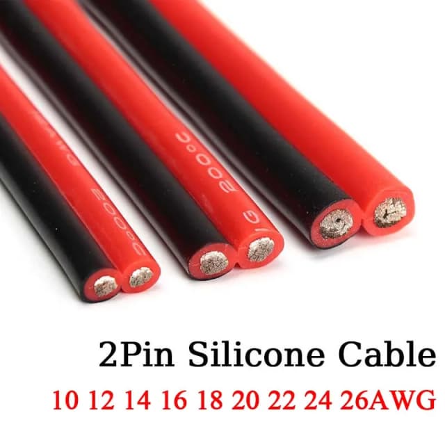
Silicone 2-pin cable 10 AWG 5m
Bonded red/black silicone pair — flexible, and the 10 AWG rung of the only silicone ladder on AliExpress that is still live
Pick 5M, 10 AWG
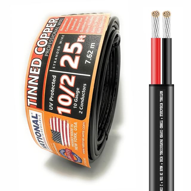
National Wire 10 AWG 2-Conductor 25ft
CL rated and ETL listed, so it is legal in a wall as well as behind a cabinet
Four runs worked out
Draw and current are at full white. The gauge is what the wire calculator picks for that current over that distance, and the drop is what it costs once picked.
WS2812B 60 LED/m, 5 m, 2 m from the supply
The standard 5m WLED reel, supply two metres away. 18 A at 5V is why the recommender reaches for cable most people would call excessive for a light.
Draw
60.6 W
Current
12.1 A
Gauge
10 AWG
Lost in the wire
0.16 V
Of supply
3.2% · Acceptable
WS2815 60 LED/m, 5 m, 2 m from the supply
Identical LEDs and length at 12V. Same power, less than half the current, and the gauge drops accordingly.
Draw
47.1 W
Current
3.9 A
Gauge
20 AWG
Lost in the wire
0.52 V
Of supply
4.4% · Acceptable
COB White 528 LED/m (24V), 10 m, 3 m from the supply
Twice the strip and a longer feed at 24V, still thinner wire than the 5m 5V run needs.
Draw
140 W
Current
5.8 A
Gauge
18 AWG
Lost in the wire
0.73 V
Of supply
3.1% · Acceptable
WS2811 FCOB 24V 720 LED/m, 5 m, 5 m from the supply
A dense addressable FCOB with the supply across the room. Distance costs exactly what current does - both are multipliers in the same formula.
Draw
105 W
Current
4.4 A
Gauge
18 AWG
Lost in the wire
0.92 V
Of supply
3.8% · Acceptable
Why the rail decides everything
The same 14.4 W/m strip, built at each of the four voltages.
| Rail | Current per metre | Feed every |
|---|---|---|
| 5V | 2.88 A/m | 2.13 m |
| 12V | 1.2 A/m | 4.25 m |
| 24V | 0.6 A/m | 8.5 m |
| 48V | 0.3 A/m | 12.75 m |
Both losses are proportional to current, and current is power divided by voltage. That single fact sets both columns: the 5V strip pulls nearly ten times the current of the 48V one for identical light, so it needs the thickest cable to reach the strip and the most feeds once it gets there. Spacing figures are the ones the power injection guide works through, and choosing between the rails in the first place is the voltage guide. The other half of the current is density, which arrives with the chip family rather than the rail — the strip types guide lists what a metre of each one draws.
Measuring it
Five readings with a multimeter, and the last one is the one that saves the wasted afternoon.
- 1
Set the strip to full white at full brightness
Drop is proportional to current, so anything less than every channel at maximum understates it. This is also the state the supply was sized for, which makes the reading comparable to what the calculator predicted.
- 2
Measure at the supply terminals first
Put the meter on DC volts across the supply's + and - output with the strip running. This is your baseline, and it is often not the number on the label: an adjustable supply may sit at 11.6V or 12.4V, and every percentage below is measured against what it actually delivers.
- 3
Measure across the + and - pads at the far end
With the strip still lit, put the probes on the last pair of solder pads on the run. Keep the supply connected - an unloaded strip shows almost no drop, which is why a reading taken with the LEDs off looks reassuring and means nothing.
- 4
Take the difference as a percentage of the baseline
Subtract the far-end reading from the supply reading, then divide by the supply reading. Under 2% is invisible, under 5% is the working ceiling, and past 10% the tail is visibly wrong.
- 5
Measure at the first LED to split the two drops
A third reading at the strip's input tells you where the loss is happening. Supply to first LED is the wire; first LED to far end is the strip. Fixing the smaller of the two is the usual wasted afternoon.
Predicting it instead
The wire half is arithmetic, so it can be answered before anything is built or soldered.
Voltage drop (V) = Current (A) × Resistance (Ω/m) × Distance (m) × 2The doubling is the return path: current goes out on the positive and comes back on the negative, so a 3 m run is 6 m of copper. Resistance per metre is a property of the gauge, which is the one term you control after the strip is chosen.
Three fixes, in order
Thicker cable to the strip
Drop between the supply and the first LED. Halving the resistance halves that loss, and going two gauges thicker roughly halves it.
Does nothing for the gradient along the strip. The copper trace inside the strip is the same width whatever you feed it with.
Feed the run in more places
Drop along the strip. Each feed resets the voltage part way down the run, so no LED is more than half a segment from a fresh supply.
Every feed has to be sized for its own current and distance. A thin jumper to an injection point moves the bottleneck rather than removing it.
Build the run at a higher voltage
Both drops at once, and it is the only fix that does. Four times the voltage is a quarter of the current for the same light, and current is what both losses are proportional to.
Decided when you buy the strip, not afterwards. It also changes which chips are available to you - the addressable families are not evenly spread across the rails.
When the honest fix is a second supply rather than more copper, the multiple power supplies guide plans the zones, the grounds and the fuses.
Questions
What is voltage drop in an LED strip?
Voltage drop is the voltage an LED strip loses between the power supply and the LED you are looking at, lost as heat in the resistance of the wire and of the strip's own copper trace, which is why a long run is dim and orange at the far end while the first LEDs look correct.
How much voltage drop is acceptable?
Under 5% of the supply voltage is the working ceiling, and under 2% is invisible. The catch is what those percentages are worth: 5% of 5V is 0.25V, of 12V is 0.6V, of 24V is 1.2V and of 48V is 2.4V. A 5V run has a tenth of the margin a 48V run has, on wire carrying nearly ten times the current for the same light.
Why is the end of my LED strip dim and orange?
Voltage drop along the strip's own copper trace. Every LED is fed through the trace running past all the LEDs before it, so the loss builds with distance and the far end runs on less than it was designed for. Blue and green need a higher forward voltage than red and give out first, which is why white slides toward orange before it visibly dims.
Does thicker wire fix a dim far end?
Only if the loss is in the wire. Thicker cable between the supply and the strip fixes an evenly dim run; it cannot fix a gradient along the strip, because the trace inside the strip is unchanged. Measure at the first LED to tell the two apart - if the voltage there is already correct, the wire is not your problem.
How do I measure voltage drop?
With a multimeter on DC volts, with the strip lit at full white. Read the supply terminals, then the + and - pads at the far end of the run, and take the difference as a percentage of the first reading. A reading taken with the LEDs off shows almost nothing, because with no current there is no drop.
Does voltage drop waste power?
Yes, and it turns up as heat in the wire. The lost voltage times the current is the wattage the cable is dissipating rather than delivering, which is why a badly undersized feed runs warm. It is a small share of the total on a sensible run, and the visible dimming is the reason to fix it rather than the energy.
Is voltage drop worse on addressable strips?
Not by chip, but by rail and by density. Most addressable families are 5V or 12V and many are dense, and both push current up for the same length of light. A 24V analog COB and a 24V addressable FCOB at the same watts per metre drop the same amount.
Enter your own current and distance to get the gauge and the drop it leaves you.
Open Wire Gauge Calculator