LED strip connectors and current
A solderless clip connector carries about 3 A continuously, and the joint at the head of a 5 m WS2812B reel at 60 LED/m carries 12.12 A - more than four times that, and on a dense APA102 reel it is 40.18 A. That gap is why clip connectors fail, and it is not a quality problem: the part is being asked for several times what it was built for. Nothing on the table below is inside a clip's rating at the head of a full reel, on any rail - a clip can feed about 1.2 m of that WS2812B. What makes a clip safe is not a better clip, it is a joint further down the run: the same connector is inside its rating from about 3.8 m onwards, because a joint carries only what is downstream of it.
What the joint is telling you
6 ways a joint fails, and what each one narrows it to. Joints go two ways - too much current through a good contact, or a contact that was never made - and the symptom is what tells them apart.
It only lights if you press down hard on the connector
The contact is touching but not clamping. A clip holds the strip against a metal tab with spring pressure alone, and pressure it only has when your thumb is on it is pressure it never had. Nothing about this improves on its own - it is the same joint that will be intermittent inside a wall.
The clip grips the strip firmly and nothing lights at all
Almost always the strip's own backing rather than the connector. Many reels carry a clear protective film over the copper pads, and every waterproof one carries a silicone sleeve. The tabs close on that instead of on copper, which feels exactly like a good joint and conducts nothing.
The connector is warm, discoloured, or smells of hot plastic
Current past the rating, and the one failure on this list the rest of the page is about. It does not announce itself first: the joint works, gets hot, and the plastic around the contact softens until the spring pressure it depends on is gone. Check what the run is drawing before replacing like with like.
One colour is missing or wrong after the joint
One contact of the four or five is not making. An RGB joint fails a channel at a time and the strip carries on showing you the other three, which is why a joint that looks half-working is usually a joint rather than a controller.
It worked on the bench and failed once it was on the wall
Movement. A joint carrying its own cable's weight, or bent as the strip was pressed into a channel, has the wire tail levering on the contact every time anything shifts. The bench had it lying flat and unloaded.
It flickers, and the flicker follows your hand
The joint, found. That is the wiggle test passing, and it is the one symptom here that needs no further diagnosis.
If the strip is flickering rather than failing outright, the flickering guide sorts a bad joint from the other things that look like one.
What a connector carries
There is no standard here. A solderless clip is a commodity part made by dozens of factories to no shared spec, and what it carries depends on how hard the tabs bite and how much of the pad they touch. These are the figures four independent sources agree on, and they are the only numbers on this page we did not compute.
| Joint | Carries | |
|---|---|---|
| Solderless clip | 3 A | The push-fit connector that comes in the box. Metal tabs press onto the strip's pads, and the contact area is a fraction of a soldered joint's. This is the figure the bench teardown found it good for continuously, against a higher number on the packet. |
| Clip, optimistically | 5 A | The top of the range sellers quote, and roughly where the community reports them beginning to smoke. Reaching it needs a clean pad, full tab contact and no flexing. It is a ceiling to stay under, not a target. |
| Soldered joint | 6 A | The conservative end of what a soldered joint carries with wire sized to match. It is not that solder is magic - it is that the joint is now the wire, and the wire can be whatever gauge the current needs. |
A number higher than 5 A printed on a bag of clips is a claim rather than a specification. The rest of this page sizes against 3 A, which is what a teardown found one good for continuously.
And what happens past it
The teardown in that list is the only source that measured anything, so it is the only one that can say what a connector does when it is over its rating rather than under it. Each sample held at current for 30 minutes, hung in free air, read with a thermal imager.
Two-pin strip-to-wire plug 3 A stated
The small white plug on the tail of most single-colour reels
- 3 A → 92°F (33°C)
- 4.5 A → 112°F (44°C)
- 10 A → 251°F (122°C)
- 15 A → 410°F (210°C) melted and smoked
Sold with 22 and 24 AWG tails, which is the other half of its limit: the wire is rated for about as much as the contact is.
5.5 x 2.1 mm barrel jack 5 A stated
The plug on the end of every desktop brick supply
- 5 A → 93°F (34°C)
- 10 A → 136°F (58°C)
- 15 A → 277°F (136°C) melted and smoked
The best-behaved of the three, and the joint nobody counts as a joint, because it came attached to the supply.
Solderless clip 5 A stated
The hinged clip whose tabs press onto the strip's copper pads
- 5 A → 114°F (46°C)
- 7.5 A → 199°F (93°C)
- 10 A → 297°F (147°C)
- 20 A → 470°F (243°C) melted and smoked
The bench's most useful finding is where the heat sits: not in the tabs gripping the strip, but where the connector clamps its own wire tails. The half everyone inspects is not the half that fails.
Two caveats, and both point the same way. It is one bench and three samples rather than a survey, so these are the shape of the limit rather than a specification - the measurements are published in full. And free air is the kindest case there is: the same connector inside an aluminium channel behind a diffuser has nowhere to put its heat. So these figures are optimistic, which is why the argument below survives them - even the optimistic ones are far under what the next table asks for.
What your joint carries
Every amp the run draws passes through its first joint, so that joint carries the whole strip. This is a 5 m run, at full white and running colour effects, because the wiring has to survive the worse of the two whether or not the strip ever runs there.
| Strip | Rail | Density | Full white | On effects | Against a clip |
|---|---|---|---|---|---|
| APA102 | 5V | 144/m | 40.18 A | 14.46 A | 13.4× over |
| SK6812 RGBW | 5V | 144/m | 34.42 A | 8.05 A | 11.5× over |
| WS2812B | 5V | 144/m | 29.09 A | 10.15 A | 9.7× over |
| APA102 | 5V | 60/m | 16.74 A | 6.03 A | 5.6× over |
| SK6812 RGBW | 5V | 60/m | 14.34 A | 3.36 A | 4.8× over |
| WS2812B | 5V | 60/m | 12.12 A | 4.23 A | 4× over |
| WS2814 RGBW | 12V | 60/m | 6.75 A | 2.07 A | 2.3× over |
| WS2815 | 12V | 60/m | 3.93 A | 4.13 A | 1.4× over |
| WS2814 RGBW | 24V | 60/m | 3.38 A | 1.03 A | 1.1× over |
The bolded figure in each row is the one its joint is rated against. On every strip here but one that is full white. The WS2815 is the exception, and it is why this table has two columns rather than one: a 12V single-addressable chip regulates each LED down from 12V and burns off the difference, so it draws slightly more for a solid colour than for white. Rating that joint from the white figure would under-rate it.
Not one row is inside a clip connector's rating — not even the 24V one, which is the gentlest addressable joint on the site. That is the finding: at the head of a full reel, a clip is out of its depth on every rail people build on. The 5V rows are not close, running 13.4× over at the worst. A clip can feed roughly 1.2 m of that WS2812B before it is over its rating.
Where the joint sits
A joint carries only what is downstream of it, so the identical connector is over its rating at one end of a reel and comfortably inside it at the other. Same WS2812B at 60 LED/m, same clip, joined in different places.
| Joint sits at | Strip downstream | It carries | Clip holds? |
|---|---|---|---|
| 0 m | 5 m | 12.1 A | No |
| 1 m | 4 m | 9.68 A | No |
| 2.5 m | 2.5 m | 6.05 A | No |
| 4 m | 1 m | 2.42 A | Yes |
| 4.5 m | 0.5 m | 1.21 A | Yes |
So the connector was never the problem — its position was. On this run a clip comes inside its rating from about 3.8 m onwards. The practical rule: solder the joints near the supply, use clips at the far end, and if one joint has to sit at the head of the run, that is the one to solder even when every other joint on the project is a clip.
Why joints fail
In the order worth checking them. The first is the current everything above measures; the rest are mechanical, and no amount of headroom fixes them.
The joint carries more current than the connector is rated for
The first thing to rule out, and the one nobody prints a number for. The first joint on a 5 m WS2812B reel carries 12.12 A against a clip's 3 A - 4 times over.
Read your own run off the table above, then take the cheapest fix that clears it: move the joint downstream, feed the run from both ends, or solder that one joint.
The tabs never reached copper
A joint that is mechanically perfect and electrically dead. The protective film over the pads is clear and the silicone sleeve on a waterproof reel is thick, and a clip closes convincingly on both.
Peel the film, and cut the silicone back past the pads on an IP-rated strip. If the strip is genuinely potted there is nothing under there to clip to - that reel wants its factory tail, or a soldered joint resealed with heatshrink.
Spring pressure is the whole contact, and it fades
Works, then works intermittently, then works only when pressed. A clip makes no gas-tight joint - it holds two surfaces together, and thermal cycling, oxidation and vibration all work at that.
Where the joint has to last, make it a joint rather than a contact: solder, or a screw terminal that can be re-tightened. Keep clips for places you can reach.
The wire tail is doing the work the adhesive should
Failures near the ends of a run, in corners, and anywhere the strip was pressed into a channel. The bench above found the hot spot at the wire clamp rather than at the strip, and that end is the weak one mechanically too.
Strain-relieve every joint. A dab of hot glue over the tail, or a cable tie anchoring the wire a few centimetres back, means movement pulls on the anchor instead of the contact.
The connector does not match the strip
Pins that do not align, tabs that miss the pads, or a joint that shorts as it closes. Strip comes in 8 mm and 10 mm widths and in 2, 3, 4, 5 and 6 pad counts, and the connector aisle does not sort itself.
Match width and pad count before anything else, and cut on the marked line - a cut through a pad leaves half a contact for the tab to find.
Three of those five have a part behind them. The wrong footprint is fixed by the right clip, a contact that fades is fixed by a screw terminal that clamps instead of springs, and a levering wire tail is fixed by a cable tie and a dab of hot glue.
The other two are not purchases. A tab that never reached copper wants the film peeled, not a better part. And at the head of a full reel nothing in the connector aisle holds — a screw terminal fixes the spring, not the current, because the strip-side contact is still a tab on a pad. What is sold as a high-current connector is wire-to-wire: barrier strips rated 15, 25 and 45 A, which are cheap and plentiful and all assume you have already got onto wire. That is the honest shape of this aisle. Getting onto wire at the head of a reel means soldering.
A clip that fits the strip
For a 3-pad strip like the WS2812B above. Check your own reel's width — the same chip is sold on 8 mm and 10 mm, and the connector does not stretch.
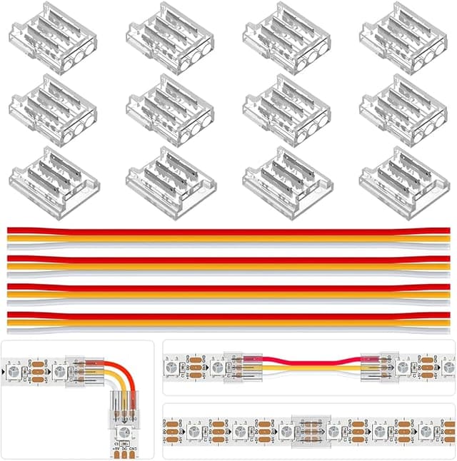
BTF-LIGHTING 3 pin 10 mm connector kit
The manufacturer's own kit, and it carries all three pieces the page names: the gapless connector for a cut, the corner for a turn, and a flying lead for a feed.
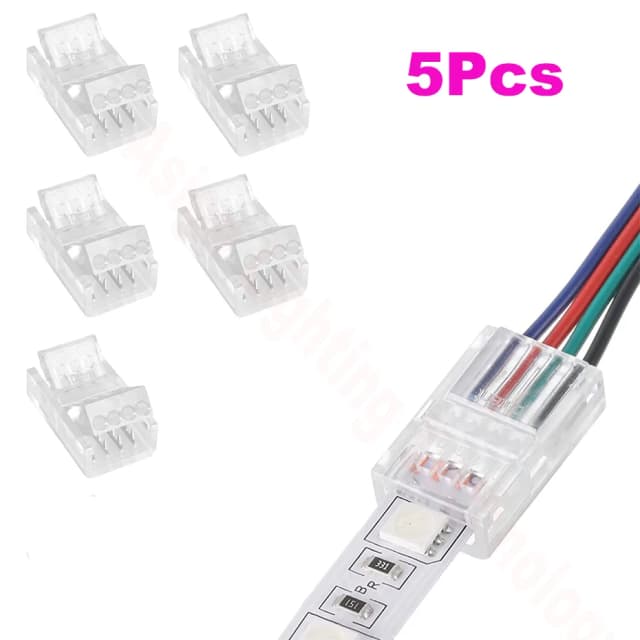
Strip-to-wire clip, 3 pin 10 mm
Pin count, width and what it joins are three separate options on one listing, so the card can name the exact variant.
Pick 3Pin / 10 mm / Strip to Wire
The same joint on a four-pad strip
SK9822 / APA102 and WS2815 carry a fourth pad — a clock line on one, a backup data line on the other — as does plain analog RGB, where the three colours are three separate wires. A 3-pad clip leaves that channel unconnected, so this is a different part rather than a tighter fit.
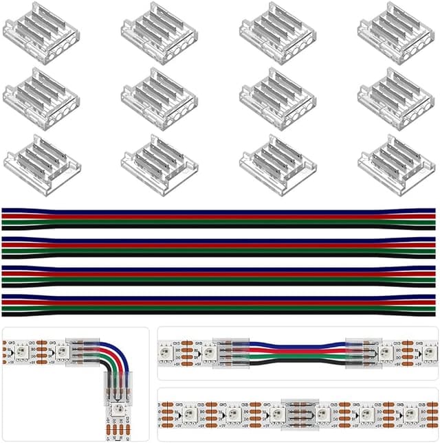
BTF-LIGHTING 4 pin 10 mm connector kit
The 4 pin twin of the kit above, from the same maker, and its own listing names WS2815, SK9822 and APA102C — every 4-pad strip this site knows about.
Strip-to-wire clip, 4 pin 10 mm
The same listing the 3 pin clip comes from — pin count is one of its option axes, so 4 pin is a variant to pick rather than a second listing to find.
Pick 4Pin / 10 mm / Strip to Wire
Worth reading the lead gauge on whichever you buy. These kits ship 22 AWG flying leads, which is a 3 A conductor — the same figure as the clip's own contact, so the two agree rather than one quietly capping the other. A kit shipping something thinner than its own connector rating would be the thing to reject.
What to do about it
In the order worth trying, because the cheapest fix is usually the one that also fixes the voltage drop you have not noticed yet.
Move the joint downstream. Free, and the table above says how far. A cut made 3.8 m along carries a third of what the same cut carries at the head.
Feed the run from both ends. Halves what each joint carries and halves the drop at the far end at the same time. This is usually the best value change on a 5 m 5V run, and the power injection guide works through where the feeds go once two is not enough.
Solder the joints that carry the most. A soldered joint carries 6 A and upwards, and the limit stops being the joint and becomes the wire — which the wire gauge calculator sizes for the current and distance you actually have.
Build at a higher voltage next time. The same light at 12V or 24V draws a fraction of the current, which is why those rails are easier on joints, cable and injection alike. That decision is made at purchase and cannot be recovered afterwards — the voltage guide makes the case properly.
Fuse what feeds it. A joint that fails open is an inconvenience; one that fails shorted is the reason the cable behind it needs a fuse sized to that cable rather than to the strip. The fuses guide is the same downstream arithmetic as the table above, applied to protection instead of to heat.
A note on what this is not. A joint running hot and a run going dim at the far end are different faults with different fixes, even though both get called "the connector". The voltage drop guide covers the second, and why strips flicker covers the case where a bad joint shows up as flicker rather than as heat.
Questions
How many amps can an LED strip connector handle?
About 3 A continuously for a solderless clip, with 5 A the top of what sellers claim and roughly where users report them heating up. A soldered joint carries 6 A and upwards, limited by the wire rather than the joint. These are vendor and community figures rather than a standard - clips are commodity parts with no shared spec, so treat a higher number on the packet as a claim.
Why do my LED strip connectors keep failing?
Almost always because the joint is carrying several times what the connector is rated for, not because the connector is cheap. A 5 m WS2812B reel at 60 LED/m pulls 12.12 A at full white through its first joint, against a clip's 3 A. The symptoms people describe - one that only works when pressed hard, a joint that browns, a section that dims after a few minutes - are what a contact does when it runs hot and oxidises. Buying a better clip buys a little headroom; moving or soldering the joint solves it.
Where should I put a joint so a clip connector is safe?
Downstream. A joint carries only the strip beyond it, so on that same 5 m reel a clip is over its rating at the head and inside it from about 3.8 m onwards. Practically: put clips at the far end of a run and solder the ones near the supply. If a joint has to sit at the head, that is the one to solder even if every other joint on the project is a clip.
Are connectors safer on 12V or 24V strips?
Far safer, though "safe" is still the wrong word at the head of a full reel. The same light needs the same watts, and watts divided by a higher voltage is less current, so the joint carries a fraction of what it would on 5V: a 24V WS2814 at 60 LED/m puts 3.38 A through its first joint where the 5V WS2812B puts 12.12 A. That is borderline against a clip's 3 A rather than hopeless, and it comes inside the rating on a shorter run or a sparser strip. This is the same reason those rails need less injection and thinner cable, and it is the strongest practical argument against a long 5V run.
Does dimming the strip make a connector safe?
It makes it safe right up until somebody turns the brightness up, which is not the same thing. Wiring is fixed at install and brightness is a setting anybody can change, so a joint has to survive full output whether or not the strip ever runs there. Size the joint for full white, then dim for whatever reason you like.
Can I just feed the strip from both ends instead?
Yes, and it is often the better fix. Feeding both ends halves what each joint carries and halves the voltage drop at the same time - a 5 m WS2812B run fed from one end puts 12.12 A through the first joint, and fed from both puts about half that through each. Past that, the answer is more feeds rather than better connectors.
Every current on this page is computed from the same engine the PSU calculator runs on, using measured per-LED draws rather than datasheet figures — see the chip reference for what each chip draws and why. The connector ratings are vendor and community figures, named in the first section, and are the only numbers here we did not measure or derive.